

.png)
_副本.png)
With the development and application of more and more high-tech automotive electronic products, how to solve the electromagnetic compatibility problem of automotive electronic system and improve the reliability and safety of automobile has become a very important and urgent problem. However, ground design as one of the methods to cure electromagnetic compatibility problem, the ground migration test is very important. Therefore, the ground design and the ground migration test are interpreted in this paper.
一、Earthing design of whole vehicle system
1.The meaning of the earth line
The ground wire is not only a junction in a car, it is an integrated system of automotive electrical system, its main functions are:
Supply DC load, AC load and transient load current loop to connect negative extremes of battery or generator;
Provide voltage to sensors, communication systems, single-ended digital input, etc.
Electrostatic shielding, isolation of external RF radiation;
Provide electrostatic discharge, ESD protection;
The ground plane of the automobile antenna;
Reduce the level, reduce the corrosion.
2.Ground wire reliability
The reliability of the ground loop is determined by the following key factors:
A connection surface of a grounded metal, including the connection between the ground floor, the grounding wire and the ground floor;
The influence of coating and lubricating oil on conductive ground connection plate and its fasteners;
Potential corrosion;
Potential mechanical degradation.
3.The symbols of grounding on the automobile and the earthing circuit. See below.

Vehicle electrical location: mainly for the generator and battery in the DC circuit, and all products in the AC circuit RF ground;

Vehicle structure: marking is the ground mark of automobile structure (such as engine, body-in-white, etc.);

Product circuit grounding: the product circuit grounding, including analog, digital use of this symbol;
4.Grounding structure diagram for real vehicles

This is the ground structure diagram used in real vehicles, in which all grounding eventually returns to the negative extremes of the battery and generator. With the increase of the frequency, the impedance of the circuit will also increase, which will eventually lead to the current flow through the unwanted loop, resulting in common-mode interference, and then produce the EMC effect and damage the product.
So people will ask why migration produces common-mode interference? When it comes to common-mode interference, we have to say differential-mode interference. Let's take a look at it.
二、Common mode interference and differential mode interference
A communication line of electrical equipment, a communication line exchanged with other devices or peripherals, having at least two wires that carry power or signals as a round-trip line, usually in addition to a third conductor. This is the ground line. The change of voltage and current has two forms when transmitting through the wire. One is that two wires are used as round-trip transmission line respectively, which we call "differential mode". The other is the two wires do the route, the earth wire to do the return transmission, we call it "common mode".

As shown above, the blue signal is transmitted round-trip between the two wires, which we call the "differential mode", while the yellow signal is transmitted between the signal and the ground wire, which we call the "common mode".
The interference on any two power lines or communication lines can be expressed as common-mode interference and differential-mode interference: common-mode interference is transmitted between the wire and the ground (shell), which is asymmetric interference. It is defined as the unwanted potential difference between any current-carrying conductor and the reference ground; The differential mode interference is transmitted between two wires and belongs to symmetric interference. It is defined as the unwanted potential difference between any two current-carrying conductors. In general, the common-mode interference has a large amplitude and a high frequency, and it can also produce radiation through the conductor, which results in a large interference. The amplitude of the differential mode interference is small, the frequency is low, and the interference is small. Figure 3 is a common module Interference.

The current of the common-mode interference is not necessarily equal, but the direction (phase) is the same. The external interference of electrical equipment is mainly common-mode interference, and the external interference is mainly common-mode interference. The common-mode interference itself will not harm the equipment, but if the common-mode interference changes into the differential-mode interference, the interference will be serious. Because useful signals are all differential mode signals. Figure 4 shows differential mode interference.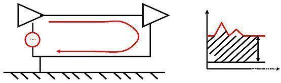
The current of the differential mode interference is equal in size and opposite in the direction (phase). The differential mode current will be converted to common-mode current due to the distributed capacitance, inductance, the discontinuity of the signal line impedance, and the flow of the signal return path through the unexpected path, etc. The differential mode current will be converted to the common-mode current.
In order to ensure the normal communication of the vehicle network, there is no wrong frame, the ground offset test of the whole vehicle is needed.
CANDT ground migration test
1. Test purpose
This test case is used to check the CAN bus communication status of the DUT during the occurrence of the offset fault state, and to check whether the DUT can recover the CAN bus communication after the fault is repaired.
2, judgment basis
During the change of ground offset voltage from 0V to 2V (the user can set the range), DUT is not allowed to have CAN bus communication failures (such as sending error frames, etc.).
Test principle and procedure

Configure control board to ground offset test mode;
Configure and power on the DUT;
CANScope normal mode connection;
The grounding voltage of the DUT is adjusted by adjusting the voltage source until the DUT stops the communication of the CAN bus.
The grounding voltage of DUT is restored to normal state (about 0V), and the data of CAN bus transmitted by DUT is recorded by CANScope.
Analyze whether the message can be received correctly and determine the result.
This test is used to verify the reliable operation of a component, such as the power supply of a component provided by the battery and the engine, the power supply voltage may not be consistent, resulting in ground offset, in order to detect whether the CAN signal can communicate normally, The CANDT conformance testing system of ZLG teleelectronics can be used.
CANDT conformance test system
CANDT conformance testing system can automatically complete the physical layer, link layer and application layer conformance test of CAN node. It is the only instrument that can perform perfect physical layer automation test and export the report in the field of CAN bus testing. The details of the structure are as follows

According to the test standard, CANDT is used to test the ground offset of each node on the bus. The results of the test can generate a report, as shown in the figure.

Upon completion of the test, the user can export an automated test report, and for failing test items, the CAN bus analyzer can be used to remove the interference and perform reliability tests to enhance the robustness of the tested equipment. And ZLG far away electronics CAN bus experts will assist users, failure to pass the analysis of the project, give recommendations for rectification;
According to the test report, we can also track the standard source of the test item, the test steps and the basis of judgment, etc.
The main plant can evaluate the quality of CAN nodes according to this report as the basis for host plant access.